While used AMD processor based servers are available in the market, power requirements for those servers make them unsuitable for my home Linux development lab. Apart from airconditioning, there is also the provision for an electric car charger that needs to be accommodated. So, I opted for a lower power rack mounted AMD processor based server using high-end desktop components. Here is how I built it.
Chassis
Server chassis are hard to find in India if you are a low-volume buyer, like an enthusiast. There are imported ones that are available in the net, but the costs are exorbitant due to shipping and customs. I focused on finding a local manufacturer and eventually found Mootek Technologies, a local manufacturer, which had 2U chassis supporting mini-ATX motherboards with less than 600 mm depth that I was looking for. Their salesperson was extremely responsive and I was able to inspect actual samples in their Bangalore office before deciding on the chassis. I chose their 2U rack mounted industrial chassis which has a depth of 400 mm.
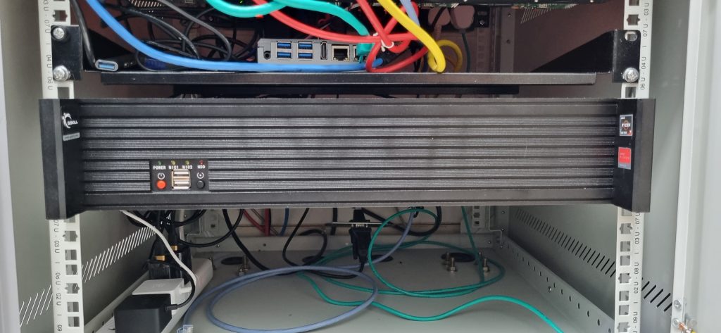
I mounted it on rail kit also provided by Mootek Technologies so that they can be pulled out as needed. I could use only the brackets for rail, not the telescopic drawer slide.
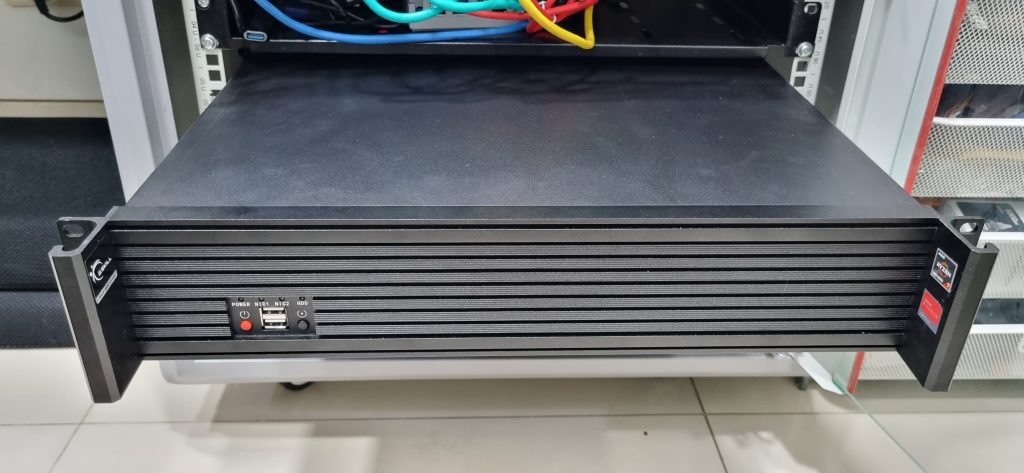
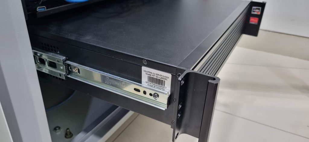
Mootek provides only 28″ rail kit to mount. However, their rail kit bracket (where the telescopic slide can be attached) is adaptable to telescopic drawer slides of any size from about 12″ to 28″ slides. So, for my 600 mm rack, I mounted the bracket in such a way that it fits the rack and attached a 14″ Hettich telescopic drawer slide (regular ones, not soft close -easily available in any Hettich outlet or online) on to it instead of the 28″ slide that came with the chassis rail kit. The bracket on each side has two parts, each to be attached from front and back. The two parts together provides a way for the external drawer slide to be attched. The inner part of the telescopic slide is attached on the side of the server chassis as shown later in this post.
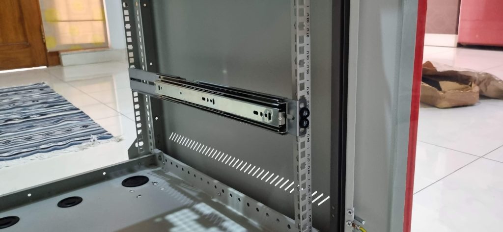
The finished rails looked like this. To do this well, the knowledge of telescopic drawer channel/slide installation is needed. I have dealt with furniture drawers with this kind of slides, so it was easy for me. Otherwise, I am sure there are YouTube videos explaing how to install these.
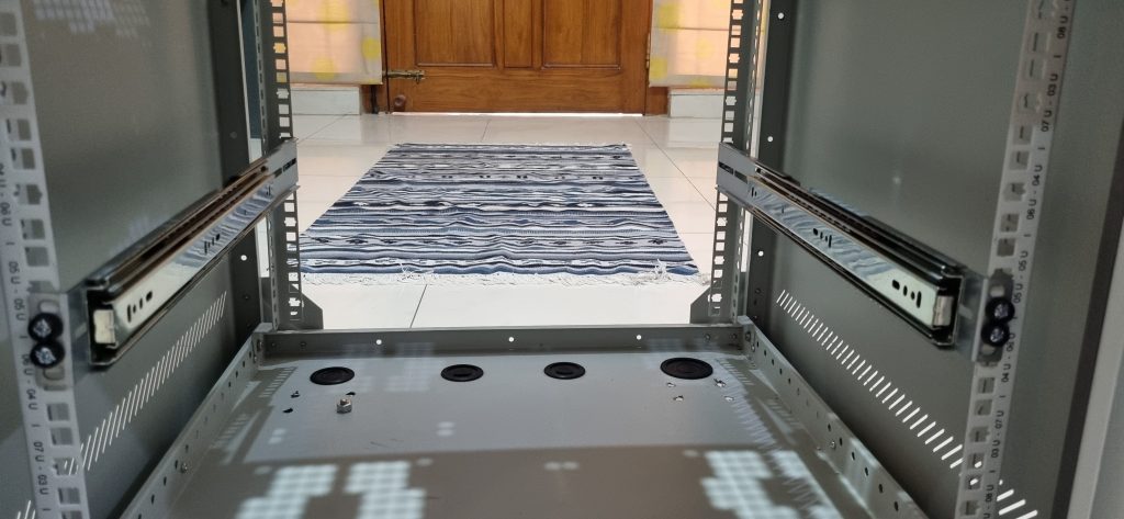
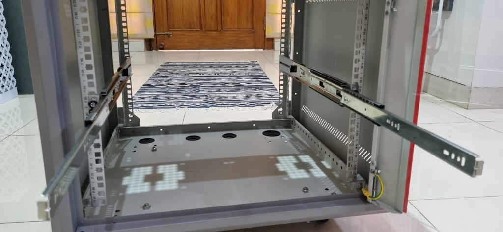
The pulled out slides looked like this.
Since I changed the drawer slides, the threaded screw holes on the side of the server chassis didn’t quite align, so I used self-tapping screws to attach the drawer rails to the chassis taking precaution that the screws didn’t touch components inside the chassis (e.g. power supply). Such work require proper tools. For metal fastening work, I use a BLACK+DECKER LD12SP 12V 10mm Li-ion Cordless Variable Speed Reversible Drill Machine Driver. Such tools are easily available online in India or at the holiest place for tinkerers in Bangalore – S. P. Road.
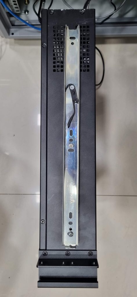
It is best to align the drawer rail to existing screw holes on the chassis where possible. Care needs to be taken to attach the drawer rails in such a way that they go into the telescopic rails correctly on either side. Hettich rails come with the plastic levers on either side which need to be pressed to push the drawer fully into the telescopic rails. There are videos describing this type of installation of telescopic channels.
This basic chassis would allow me to host other systems as well (RISC-V, Intel etc.). As long as the developer board is in ATX/mini-ATX form factor, I will be able to build a server and mount it in one of the multiple rails in my rack.
For this AMD server, I am using a Ryzen 7 processor with an ASUS motherboard, 32GB RAM and PCIE Gen4 NVME adapter. With the Mootek chassis, I had to use a specific type of power supply where the power connector and the fan are on the back side of the SMPS. Modern SMPS’ have fans at the bottom and that would not work with this chassis.
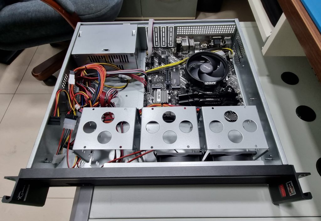
Some things to note when using 19″ rack chassis with small boards. You need long cables from SMPS to connect the board. In this case, I had to use extension cables for the 24-pin SMPS cable and 12-pin CPU power cable. These are available online as well as on S. P. Road, Bangalore.
Serial console for Linux kernel development
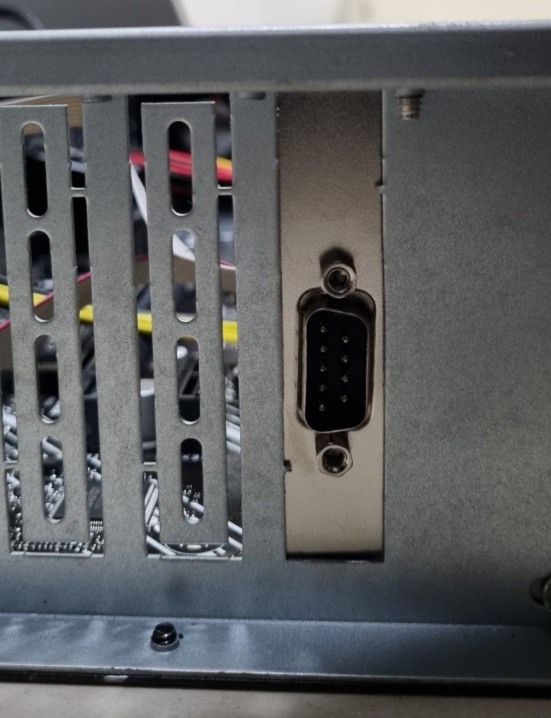
Most x86 motherboards come with a 10-pin IDC header as COM port (refer to the motherboard manual and schematics for details of this header on the board) which is not available at the back of the chassis externally. I tried using a off-the-shelf 10-pin IDC to DB9 female cable from S. P. Road, but it didn’t work as the cabling was incorrect for COM port. I was able to get a ready-made DB9 Male Serial Port Bracket to 10 Pin IDC Motherboard Header cable (procured online from Amazon) work. However, even though the description said “Low profile”, the bracket of the cable was full profile (120 mm) which is too big for my thin 2U chassis. For now, I am using it as is (hanging from the back side) but have ordered a low profile (80mm) bracket cable (StarTech.com Female 10 Pin IDC to Male 9 Pin D-sub Serial Cable, 260mm) which fits into the I/O slots on the back side of the 2U chassis.
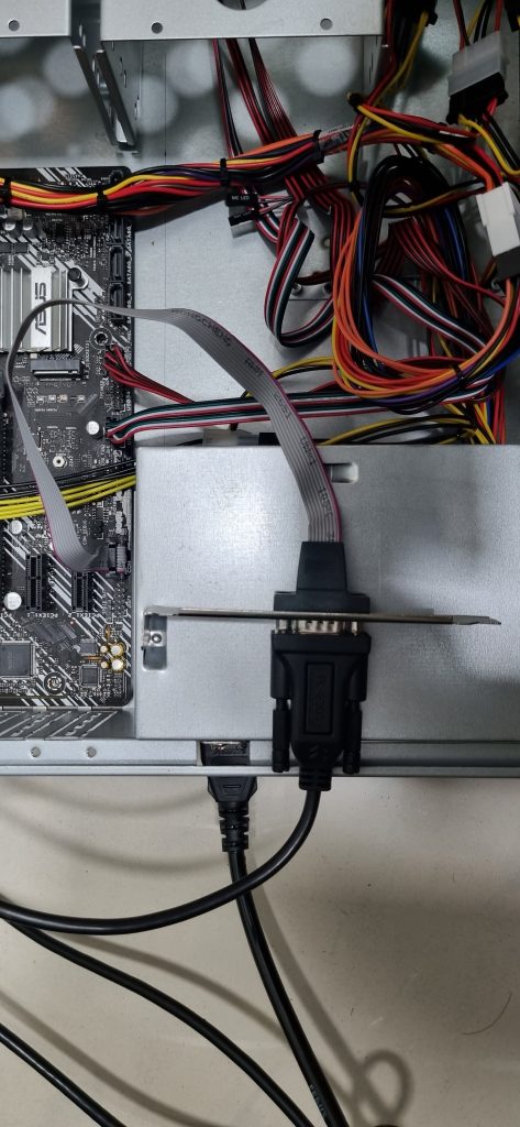
The bracket in the picture is full profile (120 mm) and hence doesn’t fit the backside slot of my 2U server. A low profile 80mm bracket will fit, something that I will do later.
To connect the DB9 COM port at the back, I am using a CableCreation USB to RS232 Adapter with PL2303 Chipset, 3.3ft USB 2.0 to RS232 Female DB9 Serial Converter Cable to connect from the terminal server to the COM port. [Update: The PL2303 based cable didn’t work reliably. I have replaced it with FT232RNL based Waveshare cable]. The terminal server setup will be described in a future post.
Update : I found a serial cable with 80mm (low-profile) bracket – StarTech.com 400mm10 pin IDC to 9 pin Dsub Serial (Product ID:PLATE9M16LP). I procured it from RS Components.
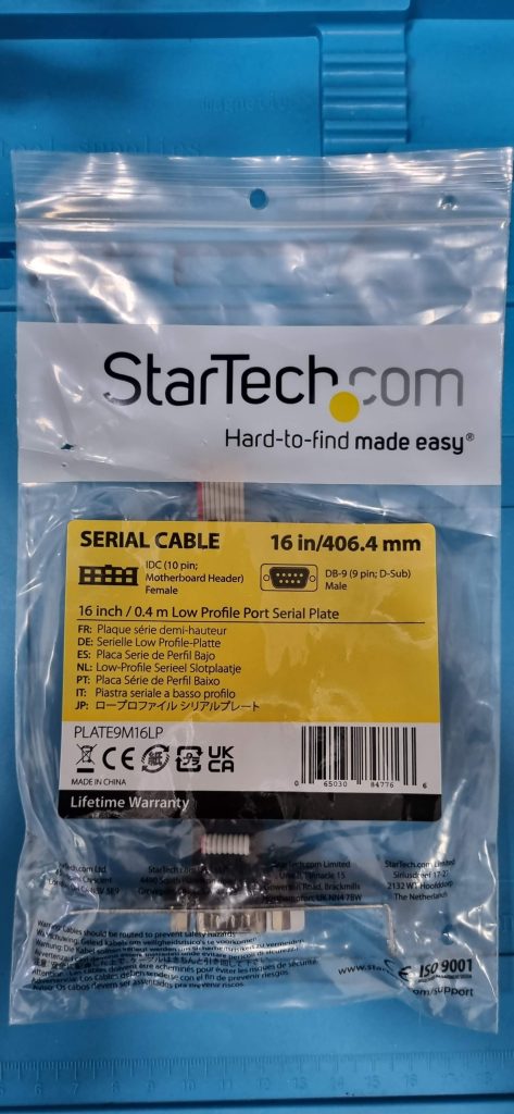
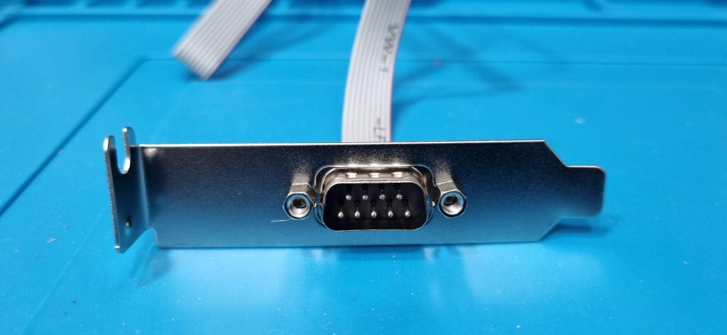
This bracket is shorter (80 mm as opposed to 120 mm for standard PCs), so it fits my 2U chassis.
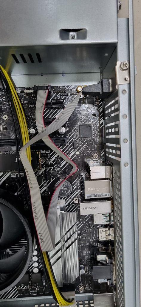
Low-profile COM port adapter (80mm) fits correctly into the 2U chassis.
Software
I have set up a PXE service through which I can network boot and install Fedora in these systems. I will describe the details of the PXE server setup in the upcoming infrastructure (future) post. The actual Linux installation part is fairly standard and is well documented (Fedora Kickstart based), so I am not going to dwell on that.
To make GRUB2 output available on serial console, I first edited /etc/default/grub to add the support for serial port :
#GRUB_TERMINAL_OUTPUT="console"
GRUB_TERMINAL="console serial"
GRUB_SERIAL_COMMAND="serial --unit=0 --speed=115200 --word=8 --stop=1 --parity=no"
GRUB_CMDLINE_LINUX="resume=UUID=1a93af54-52c7-42a1-a846-7ad4195acfff rhgb quiet console=ttyS0,115200n8"
The serial command sets up the serial communication parameters from the grub environment. For the kernel command-line, I added console=ttyS0,115200n8. By default, this is the baudrate and stop/parity configuration supported by the system. After that, I run grub2_mkconfig to generate the grub2.cfg file.
[root@x86-1 ~]# grub2-mkconfig -o /boot/grub2/grub.cfg
Generating grub configuration file ...
Adding boot menu entry for UEFI Firmware Settings ...
done
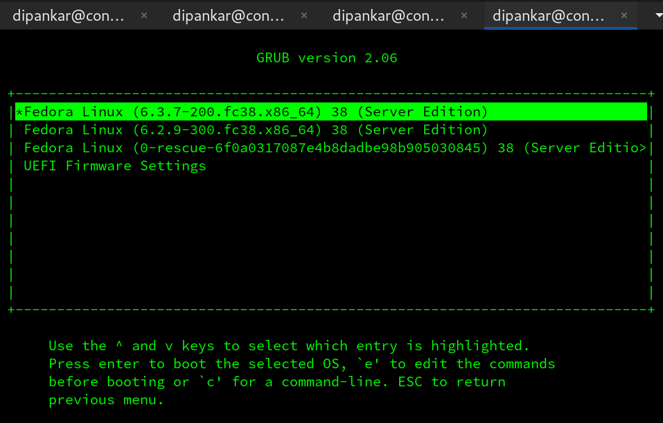
With that, I get serial console starting from grub2 menu :
[  OK  ] Started gssproxy.service - GSSAPI Proxy Daemon.
[  OK  ] Reached target nfs-client.target - NFS client services.
[  OK  ] Reached target remote-fs-p…eparation for Remote File Systems.
[  OK  ] Reached target remote-fs.target - Remote File Systems.
         Starting systemd-user-sess…vice - Permit User Sessions...
[  OK  ] Started NetworkManager-dis…Manager Script Dispatcher Service.
[  OK  ] Finished systemd-user-sess…ervice - Permit User Sessions.
[  OK  ] Started atd.service - Deferred execution scheduler.
[  OK  ] Started crond.service - Command Scheduler.
         Starting plymouth-quit-wai… until boot process finishes up...
         Starting plymouth-quit.ser… Terminate Plymouth Boot Screen...

Fedora Linux 38 (Server Edition)
Kernel 6.3.7-200.fc38.x86_64 on an x86_64 (ttyS0)

Web console: https://x86-1:9090/ or https://192.168.10.11:9090/

x86-1 login:
Upcoming posts – infrastructure services (console, PXE etc.) and then RISC-V systems.
