Starfive VisionFive 2 is a RISC-V based developer board (SBC) that was crowd-funded and released late in 2022. It uses a quad-core RISC-V CPU along with various configurations of DDR4 memory and I/O devices. This year, besides debian, ubuntu and fedora have announced support for the board. In this post, I share my experience of unboxing and integrating one of these into my home lab.
Procuring VisionFive 2 in India
There are now multiple online electronics stores in India that are selling VF2. My buying experience is limited to Rare components. I bought several of these a couple of months ago, but the costs seem to have gone up from about INR 12K to INR 14K since then.
Unboxing VisionFive 2
The VF2 comes well-packaged for long-distance shipping.
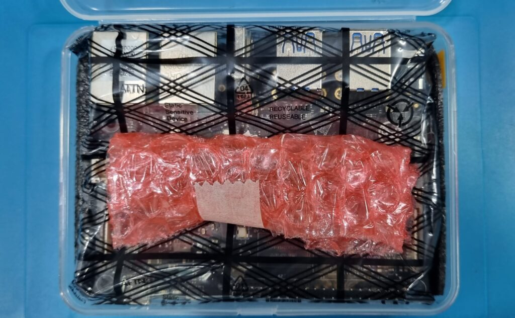
The VisionFive 2 board
The board I procured has a quad-core Starfive JH7110 RISC-V processor with IP from SiFive. JH7110 has 4 main cores (64-bit SiFive U74 RV64GC. 32KB D&I-Cache, up to 1.5GHz), 1 monitor core (64-bit SiFive S7 RV64IMAC, 16KB I-Cache and 8KB DTIM) and 1 real-time control core (32-bit SiFive E24 RV32IMFC, 16KB I-Cache) as processing elements. It supports up to 8GB DDR4 memory (which is the configuration I procured). For I/O, it has support for all the modern peripherals – USB3.0, M.2 NVME slot and two 1 gigabit network ports. It can be powered by a 15W USB type-C power supply. It also has a 40-pin GPIO header that supports common functions like serial port and fan power. A detailed specification for this board can be found here. Here are some good references for the documentation on the board :
- https://doc-en.rvspace.org/Doc_Center/visionfive_2.html
- https://www.cnx-software.com/2022/08/29/starfive-jh7110-risc-v-processor-specifications/
- Boot user guide
- Software reference manual
- Starfive github repository
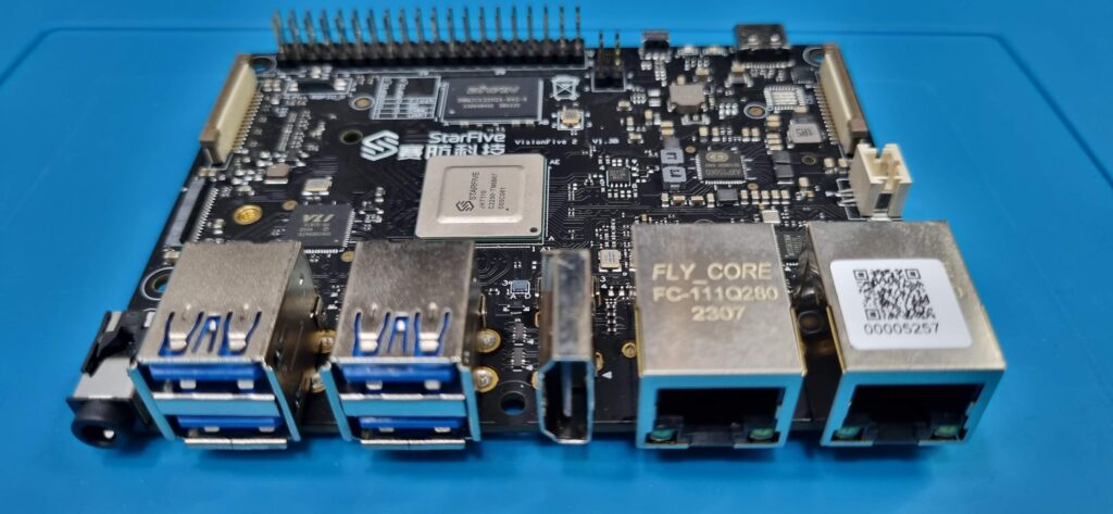
The M.2 NVME slot is on the back side of the board.
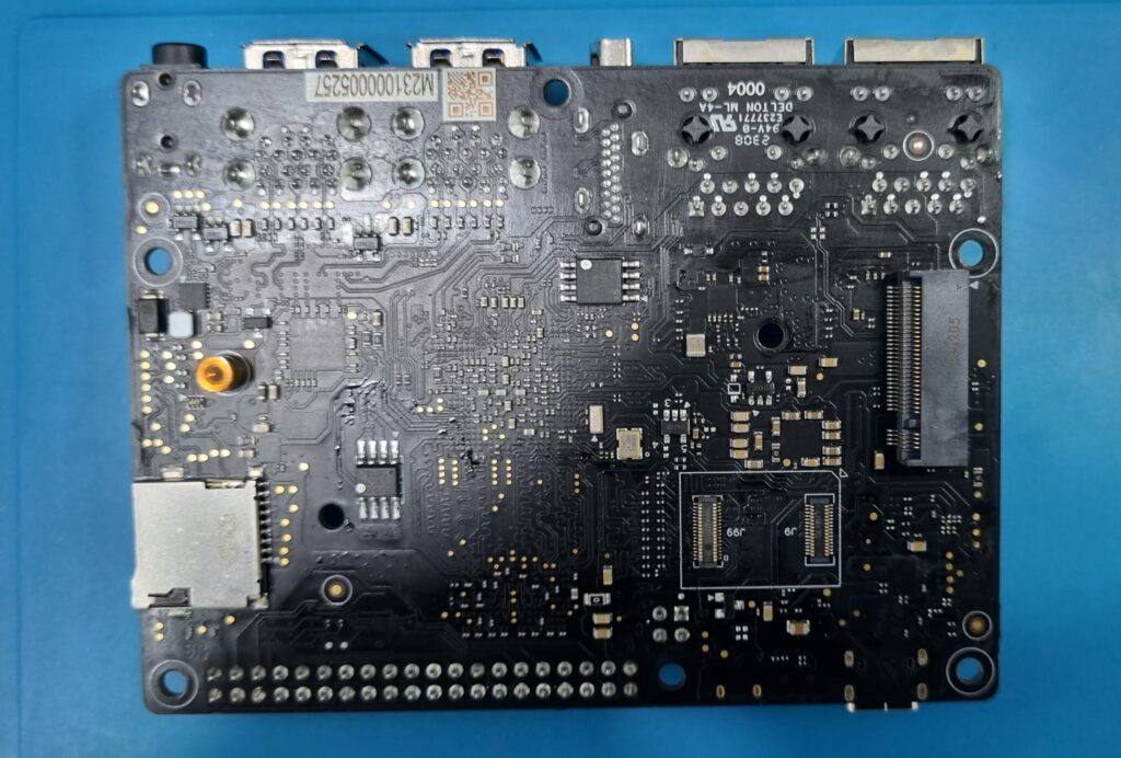
Building the VisionFive 2 box
Given that I keep all my systems and devices in a 19″ rack, I decided to put this card in a case so that it can be mounted on a tray in the rack. I used this 3D printable case design for VF2 and successfully got it 3D printed. There are multiple versions of the same case available in this design. The design has two slap-on components – the top part and the bottom part. I am using the design with 40mm fan mounting hole and grill on the top part and slots on the bottom part with 2.5mm pegs. This combination worked fine for me. For 3D printing here in Bangalore, I used 3Ding cloud printing service. All you have to do is to upload the downloaded autocad drawings to their website along with some additional inputs like material and density and pay the estimated cost online. They were fairly prompt in printing and mailing me the printed parts. I am using PLA material with 50% density and draft quality. This is good enough for my use case.
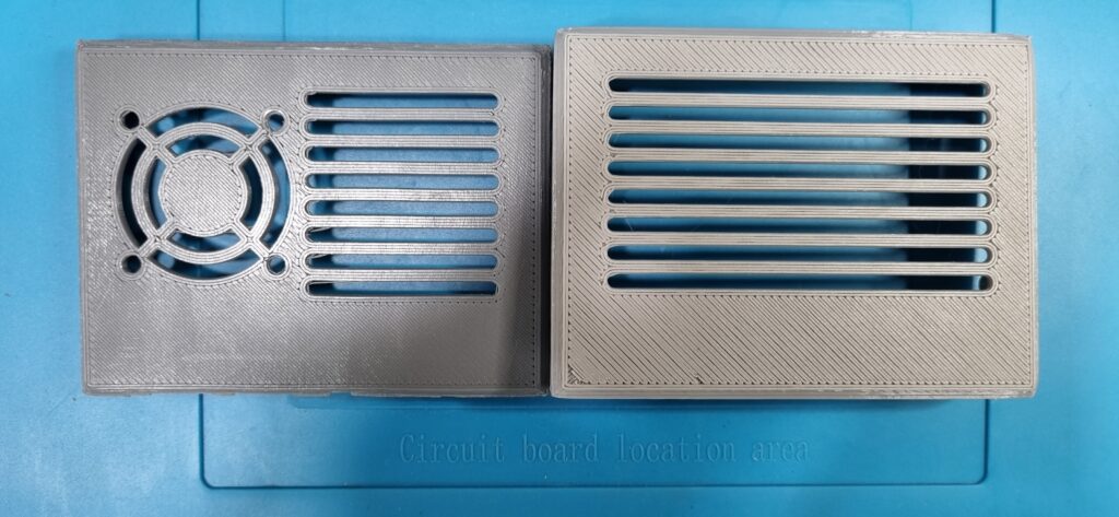
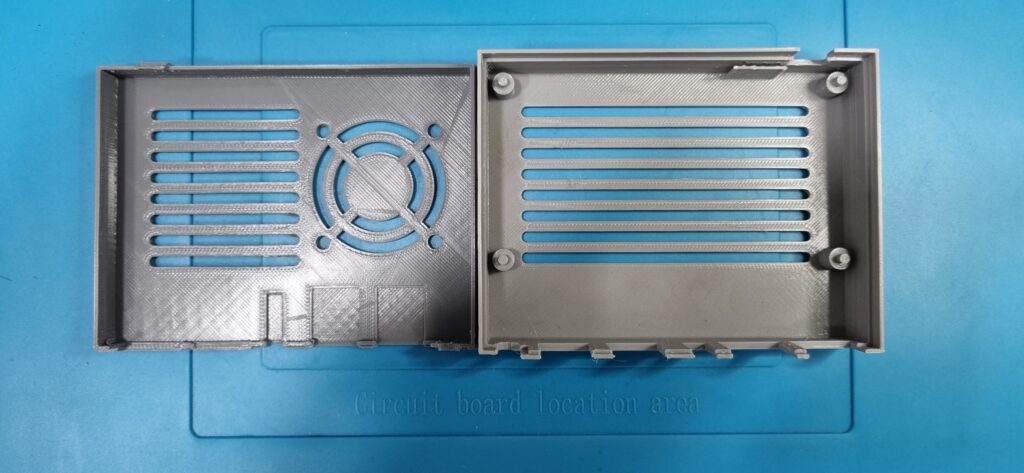
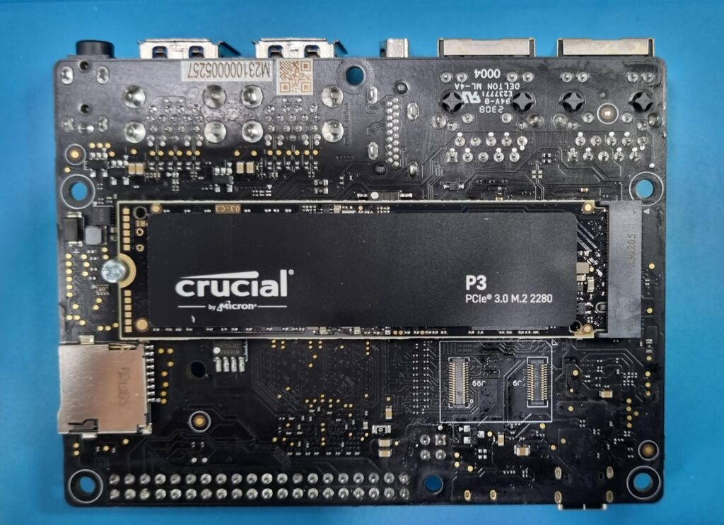
While I am using a microSDHC card for booting the board, for future experiments, I added a 500GB PCIE Gen3 NVME card to this.
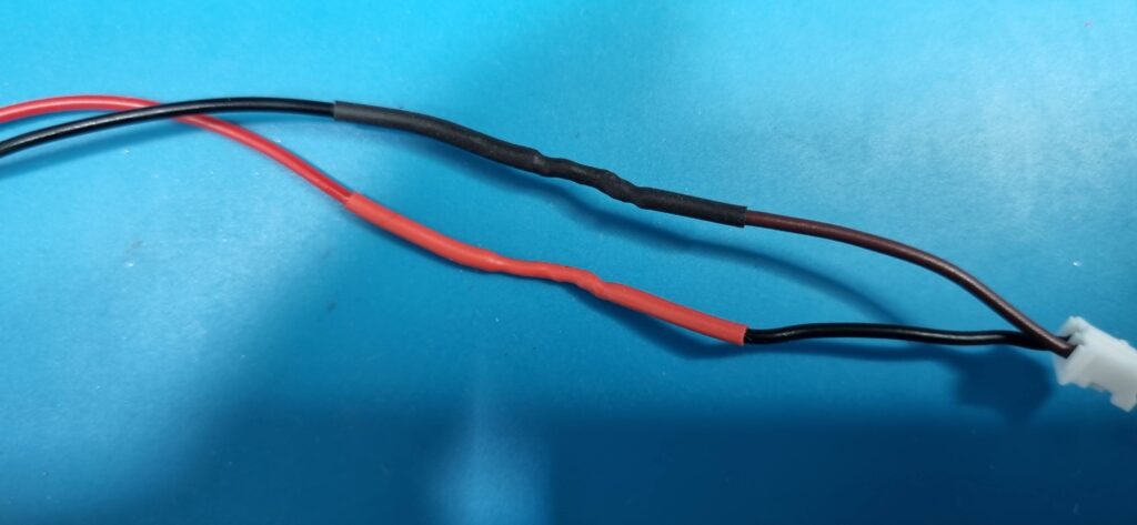
To mount the board onto the case, I prepared the board for connecting the 5V 40mm fan (procured off the shelf from SP Road, Bangalore). These fans come with a 2.5mm pitch header which can be fitted to GPIO header pins. But the VF2 board comes with a 2mm pitch header for fan and I had planned to use this rather than the GPIO fan pins. I was able to procure some 2mm pitch connectors(JST-PH 2mm pitch) with wires from Electroface Connectronics, S. P. Road and join them to the fan wire (solder, heat shrink tube insulation) to make it work.
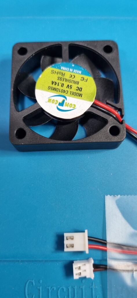
The picture above shows both the 2.5mm and 2mm connectors side by side. I followed this guide to figure out the pinout of the fan header pins. On the fan side, typically red wire indicates Vcc and it needs to be connected to the Vcc (5V) pin of the fan header. The modified fan connector with soldered 2mm connector and heat shrink tube insulation looks like the following.
The fan needs to be very low profile (10mm max) to fit into this case. I fastened the fan using 3x16mm pan head nut-bolt fasteners to the top part of the VF2 case. I have had a good experience of procuring various fasteners from Smartlink Inc, S. P. Road, Bangalore.
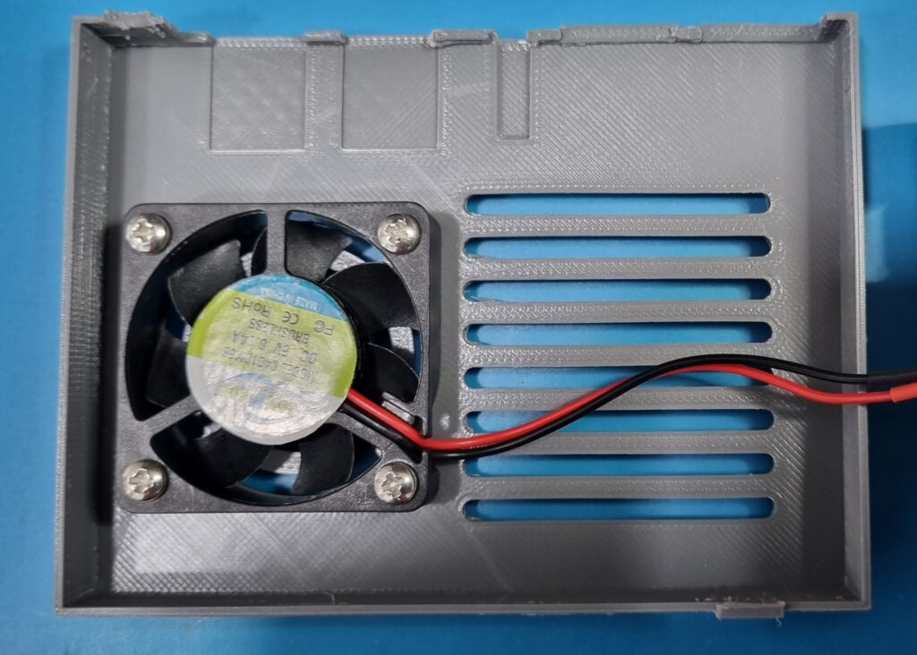
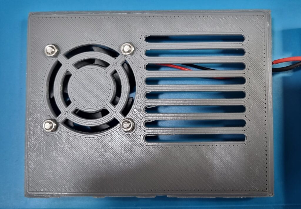
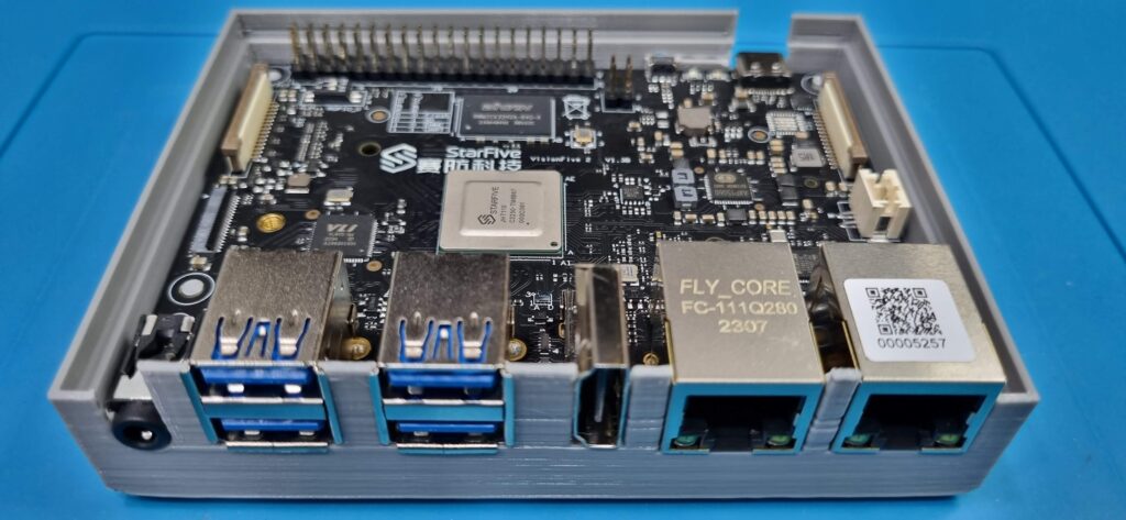
The VF2 board fits into the bottom part of the case.
The fan connector can now be connected to the header and the case closed.
Serial console for Linux kernel development
Actually, not quite. What good would it be for kernel development without the serial console support ? VF2 supports serial communication and the GPIO header has the serial communication pins. So I used a USB to TTL Serial cable (see the raspberry pi posts in this journal) to connect the serial port of the VF2 to the serial console server in my home lab. Based on the GPIO pinout, I hooked up the jumper side of the USB TTL Serial cable (Green – RX, White – TX, Black – GND going into TX, RX and GND pins of the GPIO header respectively). [Update: The PL2303 based USB to TTL serial cables I used originally turned out to be unreliable. I have replaced them with Waveshare (original) USB to TTL serial cable with FT232RNL chip. These cable have GND (black), Tx (Green) and Rx (Blue).]
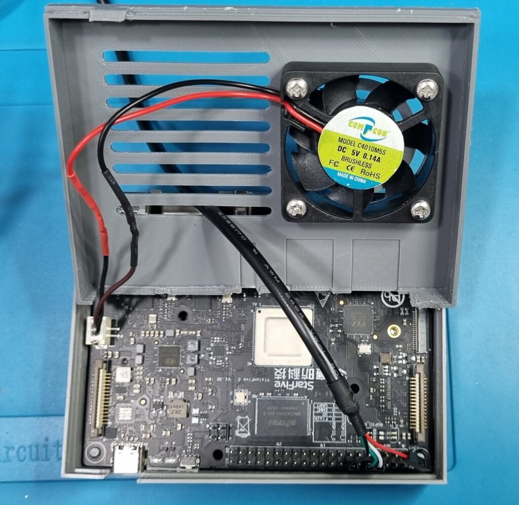
The case design by default doesn’t accommodate the full height of the jumper connectors of the serial cable when connected to the GPIO serial communication pins. So, I had to cut about 3 mm of the plastic cladding on the jumper connector (without damaging the wire) so that the top part of the case fits snugly on to the bottom part. The final assembly (with the serial console cable) is this :
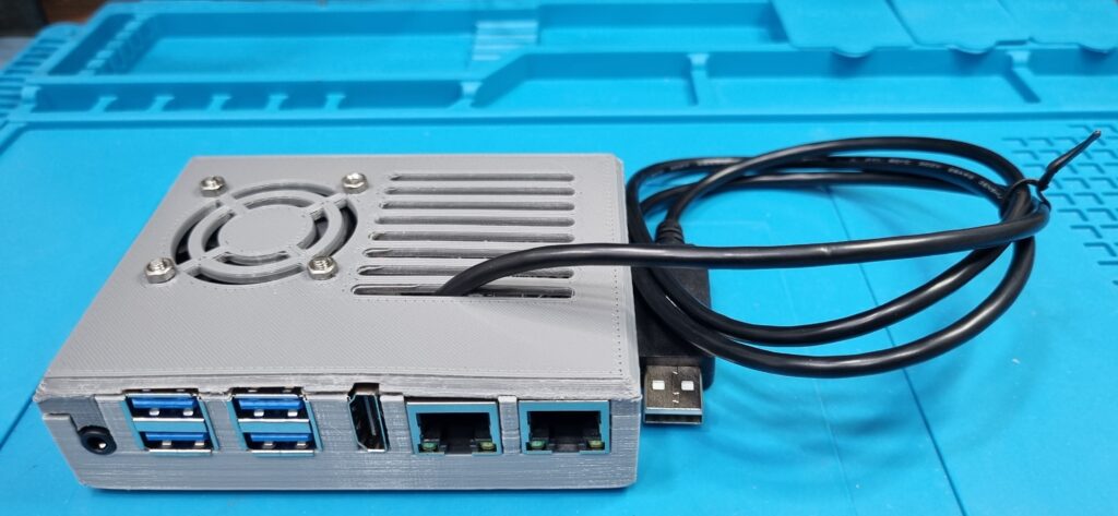
In a follow up post, I will write about the bring-up of the board with multiple distributions of Linux.
Note : I will also do a follow up post on sources of components and hardware, both online and offline stores for the benefit of people who are just starting out.
