I suspect that my friends and family think of my home network as over the top, but why anyone would not want to have a gigabit ethernet network at home is beyond me. How on earth is one going to do digital video streaming inside the house on measly 54Mbps dished out by 802.11g ? Given my plans for video streaming and the builder already had data cabling plans, I decided to go all the way and build a gigabit network connecting all parts of the house instead of relying on wireless only. Besides, boys need toys.
Here is a chronicle of what I did to build the home LAN.
If you have a new home under construction and want to play digital video content out of a local server or worry about wireless signal covering two or three stories of a concrete house (it won’t), you may want to think of building a home LAN by running ethernet cables from various parts of the the house to a common point. In houses with concrete walls (as common in India), the cables should be run through their own 3/4″ conduits separate from electrical conduits. Installing the conduits post construction requires major masonry work after cutting the wall, not to mention the paint work. It is ideal to get this done at the time of the construction of the house itself. I would recommend at least cat5e cable if not cat 6 cable for this so that you can go 1000Mbps. 100Mbps networks are so passé! Drywall houses, as common in the US, are, of course, much easier to retrofit with new cabling.
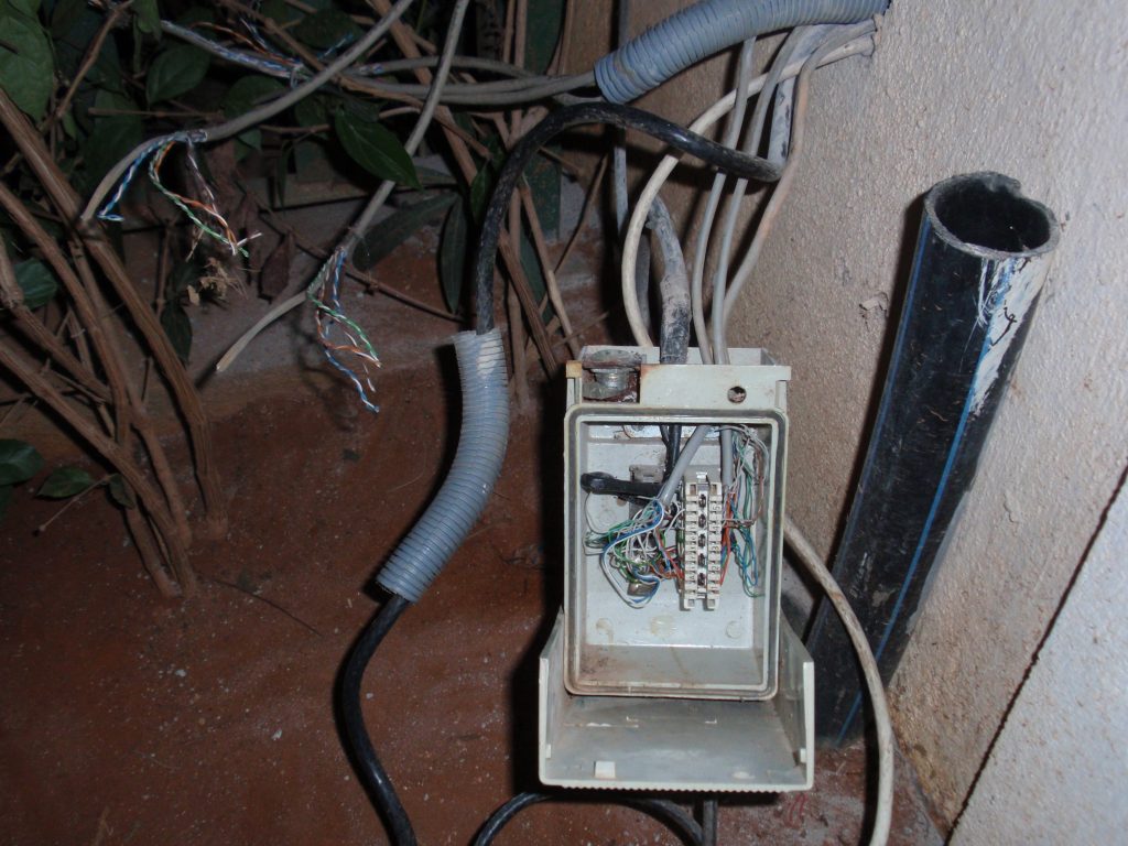
My building contractor had wired up the house with DLINK cat5e as per their original electrical plans, but they didn’t know what to do with the wirings. They laid cables from RJ-45 ports in every bedroom, each of the two offices and one from the upstairs living area where I had planned to set up a large screen TV with a media center. They landed all these cables at the telephone junction box outside the house where it was impossible to house a network router. A dangling pile of cables is what I was left with after construction. What you see in this picture is the telephone box hanging in my backyard amidst the cat5e cables before I started on this project.
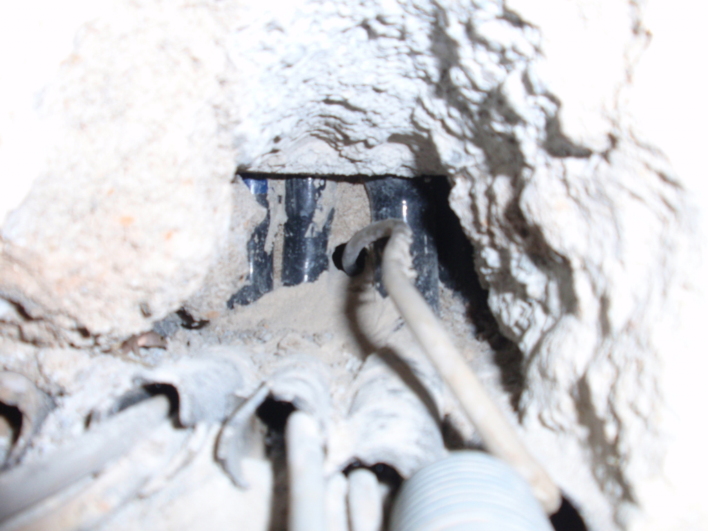
Since installing weatherproof networking equipment in the outdoor box was not an option, I drilled into the wall and rerouted the ethernet cables back into the house. Full re-routing of the conduits would have required me to break 2-3 feet of the concrete wall along the conduits. Jointing and fixing old conduits in concrete walls is also messy work that I was keen on avoiding.
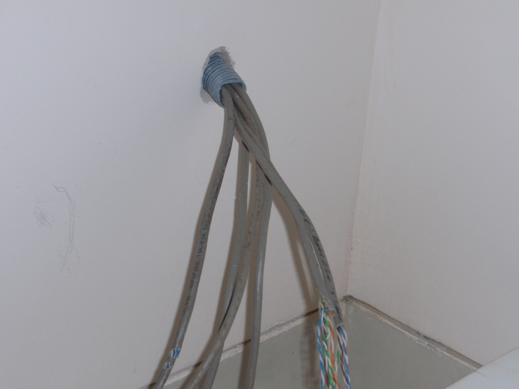
I used a flexible electrical pipe (1″ standard available at electrical goods stores) for the last few inches inside the wall in order to avoid such large masonry work. The end result was that all the cat5e wires now landed inside the house through the flexible pipe. I also routed a telephone wire (3 pair standard) from the telephone box outside into this bundle of cables so that I could hook up ADSL modems later on.
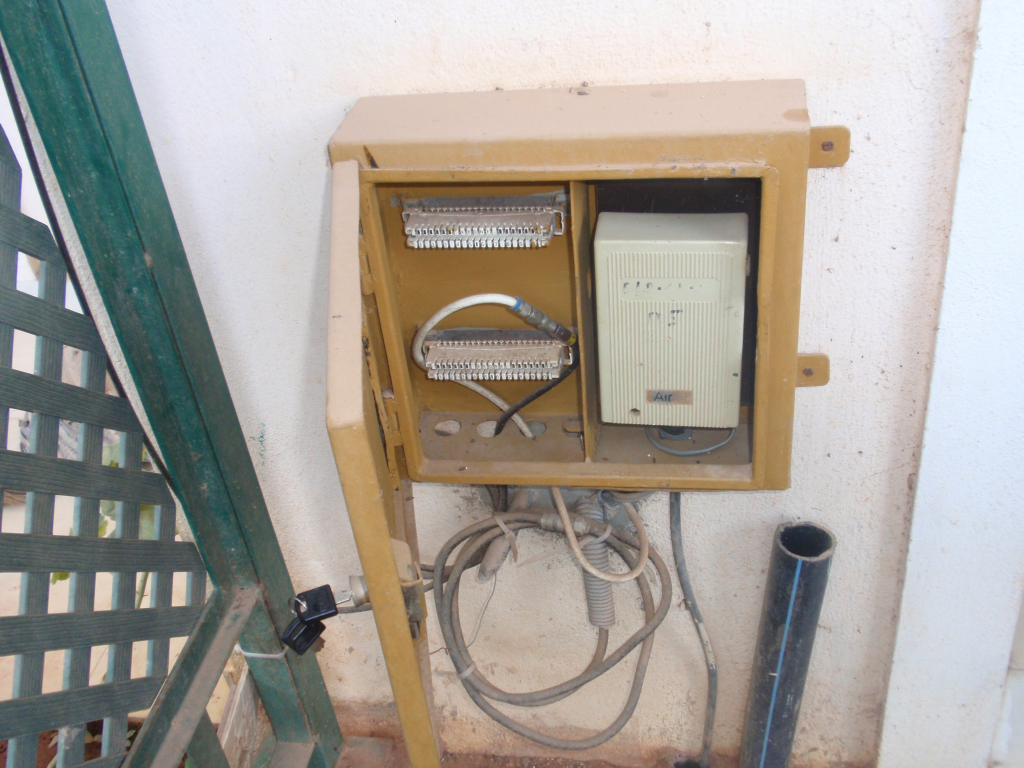
I repainted an old steel box left behind by the builder (no, I didn’t choose the color), fixed a lock (had to find a good steel works guy in the neighborhood before the first one messed up the work) and housed the telephone junction box inside it. Once I mounted the box covering the wall conduit exit point, I was done. It is now a natty cable box in my backyard.
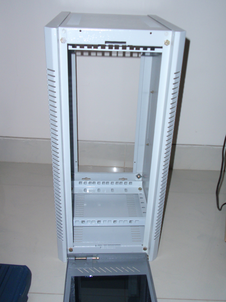
Next up was a good cabinet to hold all the networking equipment. I was pleasantly surprised to find out how easy it was to get computer equipment like 19″ racks and patch panels in retail in India. A couple of visits to S. P. Road in Bangalore and I learnt quickly that I didn’t need to bring electronic equipment from the US with me any more. I picked up many components from Railtron Electronics on S. P. Road. For this project, I bought the 4U rack you see on the left to house all the networking gear.
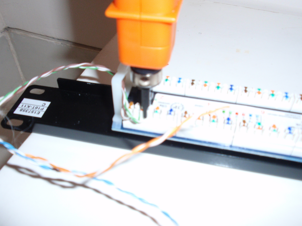
Then came the wiring of the ethernet patch panel. I used a 16-port patch panel for standard 19″ racks. For those who don’t know much about ethernet wiring, here are some good primers – this and this. Patch panels are usually color coded, you just need to decide whether you are going to use 568A or 568B throughout the house. I used 568B throughout the house. You need a telephone wire punch (available at Railtron Electronics, S. P. Road) like the one I am using in the picture to punch the wires onto the back side of the patch panel. A and B on the back of a patch panel stands for 568A or 568B. Once the wiring was done, I fitted the patch panel snugly onto the rack using the rack rail screws.
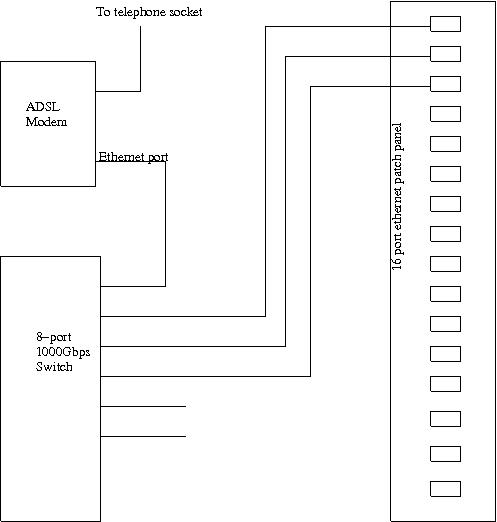
For any network, you need to have a basic architecture planned. I kept mine simple. An ADSL modem provided me the outside connectivity. The ADSL modem also provided DHCP services inside the home LAN. I put the modem in router mode for this and allocated the home LAN an address range of 192.168.10.1 to 192.168.10.254, the router being 192.168.10.1. The ADSL router also provided the DNS service. I needed the option of hooking up the modem with any of the 3 phone lines, so I got a 3-port telephone connector from Nagpal Electronics, a very quaint electronics shop on S. P. Road. With that connected to the telephone lines which I brought into the 4U rack from outside, I was ready with the external connectivity. For the internal home LAN, I bought a 8-port gigabit switch (DLINK DGS-1008D). I chose it because it was simple and energy efficient. Once I put it inside the 4U rack (it is much smaller than the standard 19″ racks equipment, so had to hang it from the rack wall using its wall sockets) and connected its ports with short 568B cat5e ethernet cables to the ethernet patch panel, I was done.
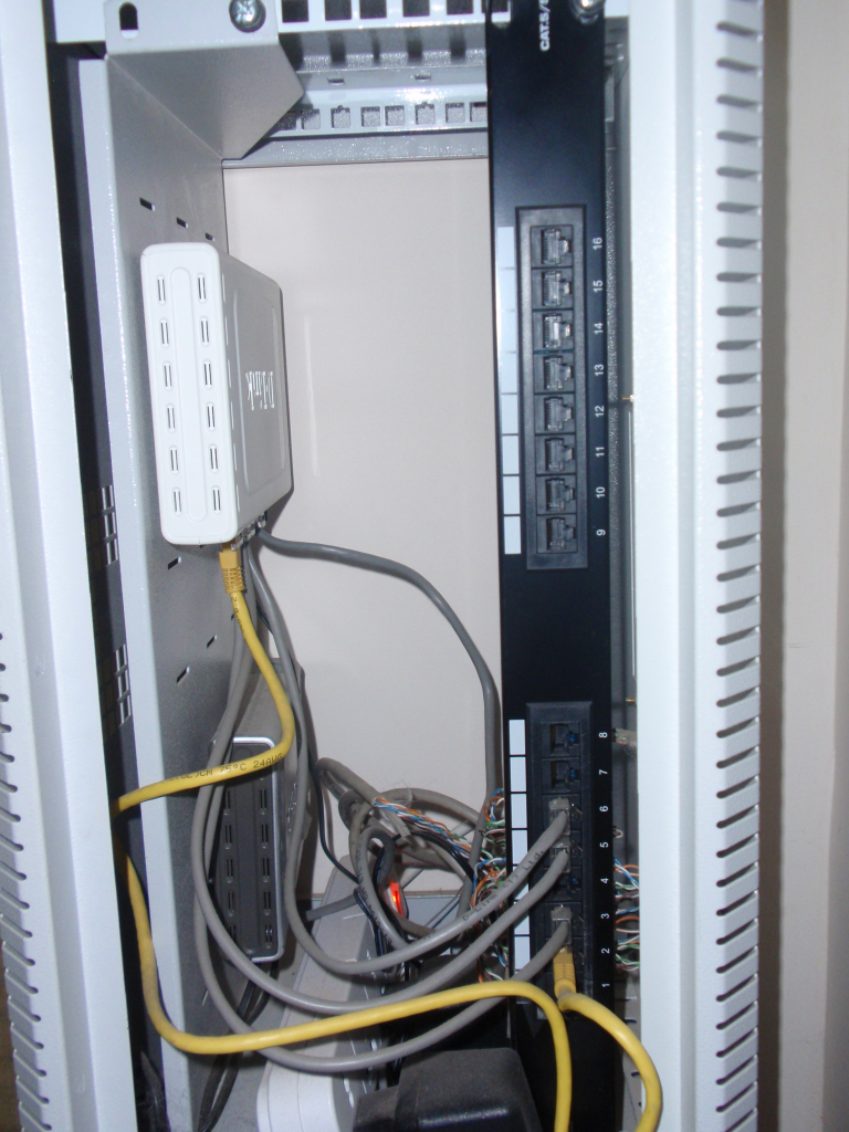
The final assembly looked something like this. The patch panel is to your right. The gitabit switch and the ADSL modem are hanging from the rack wall to the left. I backed up the whole thing using a 500VA APC UPS so that my network connectivity never gets interrupted.
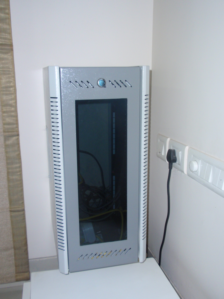
Finally, closed the door of the 4U rack and I had a nice little network center tucked away in one corner of a room. Over the top, maybe. Fun to build, hell yeah!
I added a few things on top of this setup to make the whole house really wired or wireless as it may be in this case. For wireless coverage, I connected two old wireless routers to the home LAN, one in each floor of the floor of the house. Since I wanted all of them to be in the same LAN, I disabled the routing function in each of them and connected the wireless routers to the wall sockets of the home LAN using one of the 4 LAN ports in each of them (and not the uplink port usually connected to ADSL modems). This makes them work as an wireless access point only. Any wireless device (like a laptop or a smartphone) connected to these access points would automatically get its dhcp service from the ADSL router (my centralized router and DHCP server as well) in the network center described above and all of them would be in the 192.168.10.x home network.
Some notes on equipment for home networking – you need some tools to do the job right. I used a Extech TG30 Wire Tracer Kit (not sure if this is available in India) to trace and repair the cat5e cabling partially done by the contractor. Unlike drywall houses, conduits in concrete walls make it near impossible to trace wires without such a tool. The wire punch tool I use is an HT-314B punch bought from S. P. Road. This is the standard telephone wire punch.

Two of my hardware dealers who supply my fix. Golcha IT is the new one and I have been pleasantly surprised by their resourcefulness.
Leave a Reply